Power systems engineers are critical to power supply and generation. They work at utility companies, wind turbine manufacturers, as well as aerospace and defence companies. Electrical power systems engineers find fault failures in power networks, design substations, work on power system protection, do load flow analysis, protect against arc flashes and more.
These engineers need validated tools that help them solve complex problems – and a mathematics tool is central to this work. Math and data analysis tools may be used for simple design calculations, data analysis, and more intensive mathematical tasks.
This whitepaper explores a variety of applications within electrical power systems engineering. Each application is created using Maple, with sections of each Maple document displayed to show the mathematics and algorithms required for a solution.
In this whitepaper, a total of 9 applications are outlined, covering a wide range of important tasks that an electrical power system engineer might face:
This application analyzes a five-bus power system, and calculates the voltages and powers (real and reactive) at each bus.
For larger power systems, there can potentially be thousands of buses, and efficient numerical techniques are needed to solve the system nonlinear equations. Dedicated tools are available to define and simulate larger power flow systems.
Smaller systems can be modeled and studied in Maple, to reinforce theory, investigate numerical techniques, or to try out different topologies.
This application demonstrates two approaches to numerically solving the load flow equations:
See the full application online on the Maple Application Center.

Heat is generated when current flows through a cable. The ampacity of a cable is the amount of current a cable can carry without exceeding its temperature rating. Accurately estimating ampacity is critical to minimizing the total lifetime cost of a cable installation, and minimizing maintenance issues.
Nehers and McGrath (1957) published a steady-state method to compute the temperature rise in cables. This method forms the basis of the cable ampacity tables in The National Electrical Code (NEC) 2017 and IEEE 399-1997.
This application implements the Nehers-McGrath equations and cross-checks the results against those tabulated in the NEC; the good agreement means that this worksheet can be the basis of more complex cable ampacity calculations.
The NEC gives cable ampacity for a range of standard conductors, cable arrangements and duct configurations, and assumes
This narrow range of conditions is not always applicable. For example, the southern US states often reach a soil temperature of 25°C at a depth of 36 inches, reducing the ampacity by 5% or more.
Implementing the Nehers-McGrath method in Maple can assist electrical power systems engineers with modeling non-standard configurations.
See the full application online on the Maple Application Center.

Substation earthing systems are a grid of buried conductors, known as an earth mat. The grounding of substations is very important for both personnel safety and to provide a discharge route for the overall power system.
This application calculates the cross-section of metallic tape to earth a conductor for a 110/30 kV substation.
Using Maple, the application follows EN 50522:2010 and IEC 60287-3-1 to gather soil resistivity data and current calculation equations, and features natural math notation and units throughout the calculations.
The Maple worksheet can also be converted to an interactive application with buttons and sliders, and can be deployed free of charge using the Maple Player.
See the full application online on the Maple Application Center, including the interactive calculator.

Power swings are disturbances in a power system, and are caused by caused by load changes, line switching, loss of generation, and other power faults. These can result in potentially dangerous spikes in current.
Electrical power engineers need tools and methods to analyze power swings. This assists them in devising preventative measures that eliminate the potential for costly whole system failures.
Power swings result in a loss of synchronism between the interconnected generators, and these generators run out of step. In that case, out-of-step protection schemes are used to protect the entire power system.
For example, if power swing and the condition of out-of-step are severe, certain transmission lines are tripped on the system. This separates parts of the grid into sub-grids.
As an example, consider this two machine system.

The Swing equation describes the behavior of the rotor dynamics.

The total equivalent momentum, M, is subsequently calculated, along with the line electrical power, Pe. The trajectory of equivalent impedance (which is detected by the relay in the system placed close the Bus S) will be in the protective region of the relay. So, if power swing is stable, the impedance due to the swing will return and exit the region. On the other hand, it will traverse the relay characteristic when the swing is unstable.
By analyzing the impedance behavior and transient state of the Swing equation, the required information to determine the appropriate settings for the protection can be obtained.
See the full application online on the Maple Application Center.

Large currents are generated when induction motors are started. This is called the inrush current, and is much larger than the rated current. After start up, the inrush current gradually reduces and the motor begins to rotate. The current falls to the normal operating level when the motor reaches the full running speed.
The motor needs several levels of protection to guard against out-of-specification start up conditions
The overcurrent relay or the impedance relay protects the motor from an abnormal current due to short-to-ground faults and motor overload conditions. However, the relay needs to withstand the extreme current spike of inrush current during start-up for a short period.
Thus, by analyzing the transient trajectories and the impedance of the motor, the appropriate relay settings can be determined.
This application shows how to analyze the transient behavior of a motor with impedance and torque characteristics, obtained from an equivalent circuit model of an induction motor. The application also demonstrates a protection scheme study based on these result of analysis.
Key topics covered in this application are below. The full calculations can be found in the Maple application online.
See the full application online on the Maple Application Center.

In this application, you can numerically invert the Laplace transforms that describe the voltage and current in a transmission line. This requires fast, efficient numerical algorithms, fluidly connected to a broader toolset of plots and documentation.
The calculations begin with a lumped parameter model of a transmission line, which can be represented as coupled, partial differential equations after applying Kirchoff’s voltage and current laws. The Laplace transforms are based on these resulting differential equations which are known as the Telegrapher’s Equations, as seen below.

The results describe the transient variation of current and voltage at any point on the transmission line.
See the full application online on the Maple Application Center.

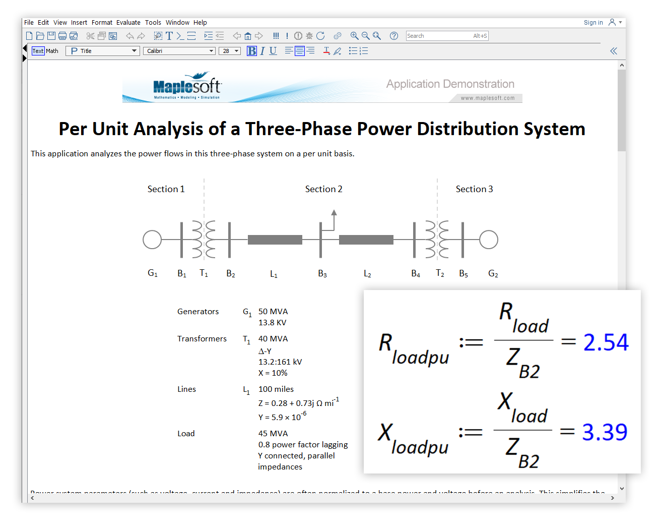
This application analyzes the power flows in a three-phase system on a per unit basis.

Power system parameters (such as voltage, current and impedance) are often normalized to a base power and voltage before an analysis. This simplifies the analysis of the power flow in the system; for example, for a transformer, you can ignore turns ratios of transformers.
The units generally used in power systems studies are built into Maple. For example, Maple understands what volts, amps and ohms are, and correctly converts units into derived quantities. Custom units can also be defined in Maple, and are used in this application to simplify the mathematics.
See the full application online on the Maple Application Center.

An arc flash is a violent eruption of heat and light caused by an electrical explosion. Arc flashes can seriously injure electricians, with fierce burns posing a significant risk to life. Other hazards include shrapnel and a pressure wave (often called an arc blast).
The electrical explosion results from an unwanted electrical connection through the air, perhaps to ground or another conductor.
To protect from the effects of an arc flash, electricians working on high-power equipment must wear protective clothing when within the hazard zone, and be aware of how far that zone stretches.
This application determines the minimum safe working distance from an arc flash, following the empirical methodology presented in IEEE 1584 - 2018. Specifically, the application calculates the:
The system studied is a high voltage 15 kV switchgear. The electrode configuration can be switched between VCB (vertical conductors in a metal box, VCBB (vertical conductors terminated into a metal box's insulation barrier), HCB (horizontal conductors in a metal box), VOA (vertical conductors in open air) and HOA (horizontal conductors in open air).
See the full application online on the Maple Application Center.

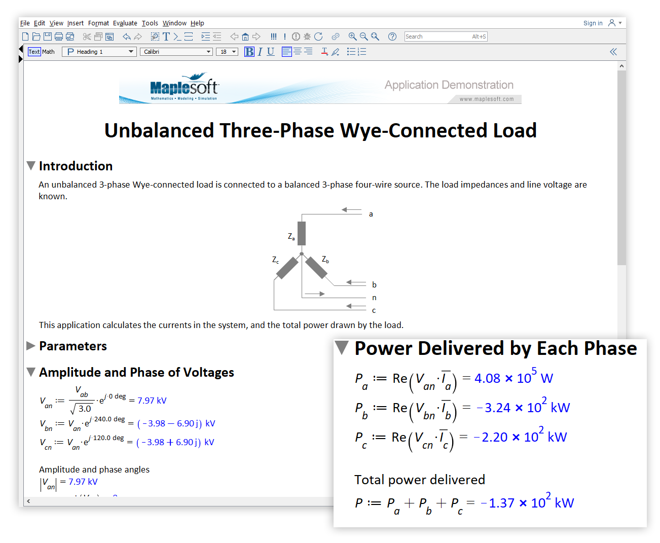
An unbalanced 3-phase Wye-connected load is connected to a balanced 3-phase four-wire source. The load impedances and line voltage are known.
This application calculates the currents in the system, and the total power drawn by the load. This requires a calculation of the relevant amplitude and phase voltages of each system component.
The built-in units system in Maple is used to define the load impedances and line voltage, in order to simplify the need for additional calculations the engineer might be required to perform.
See the full application online on the Maple Application Center.
